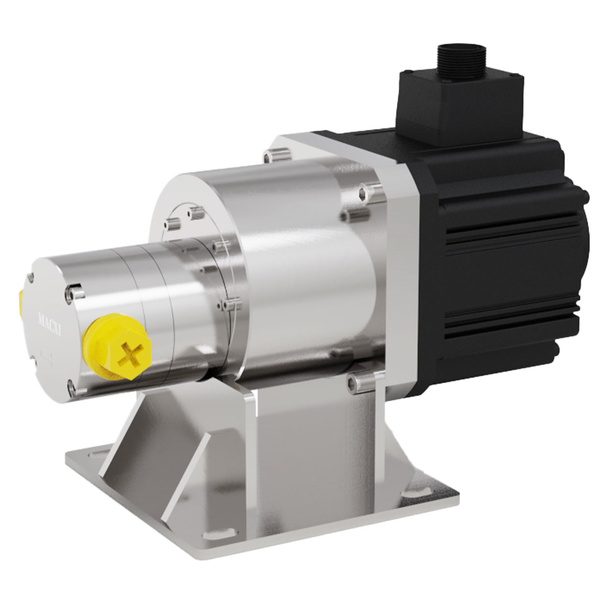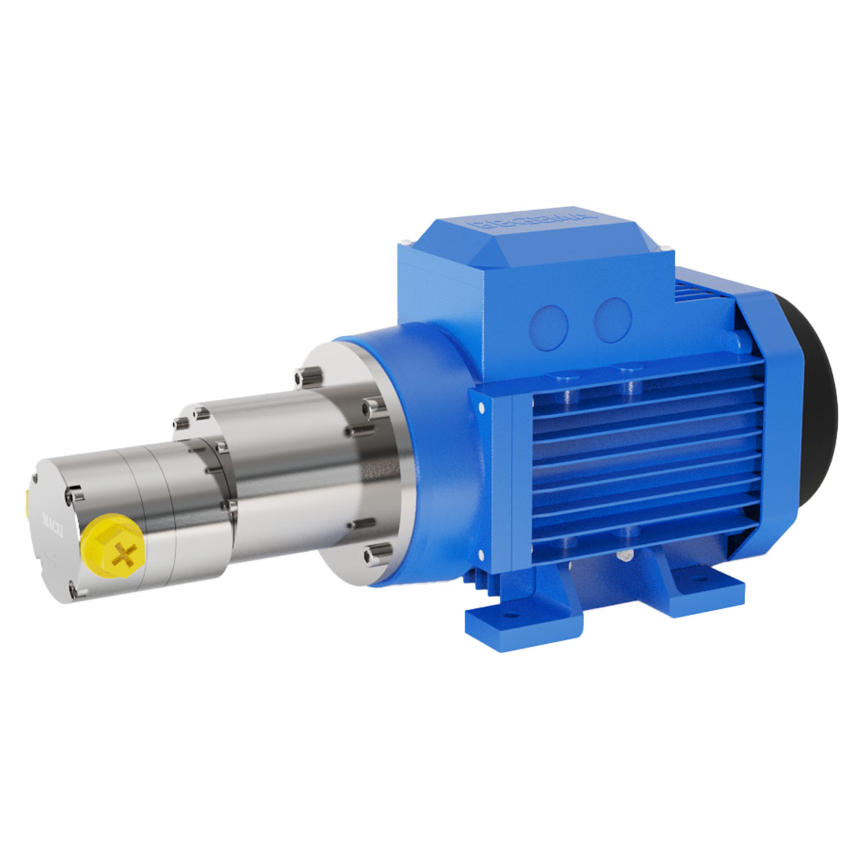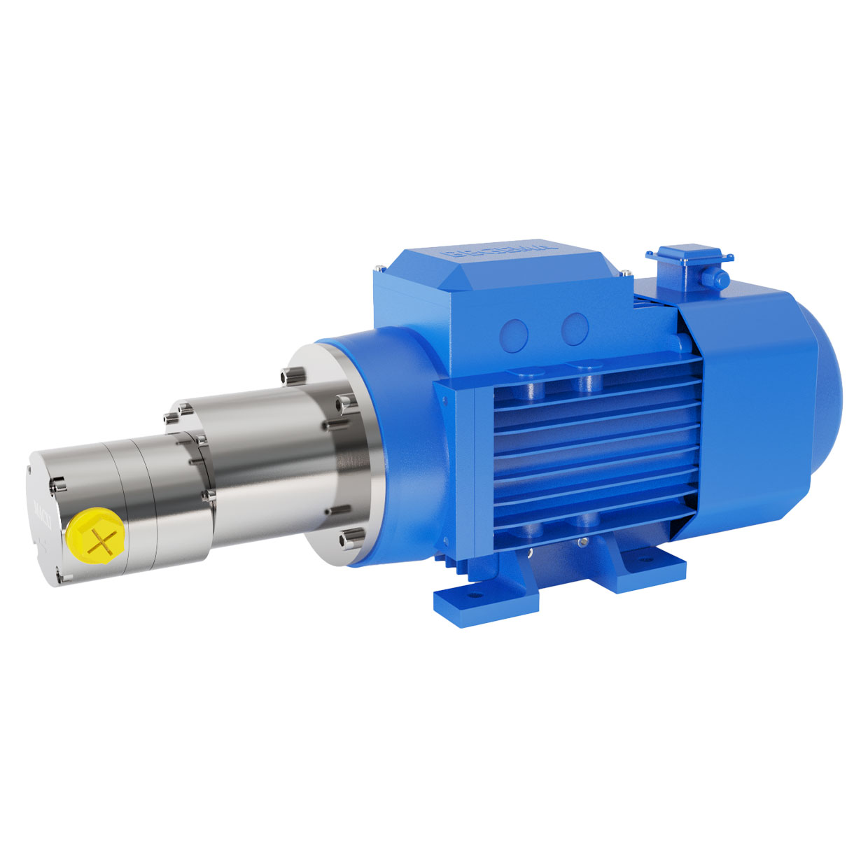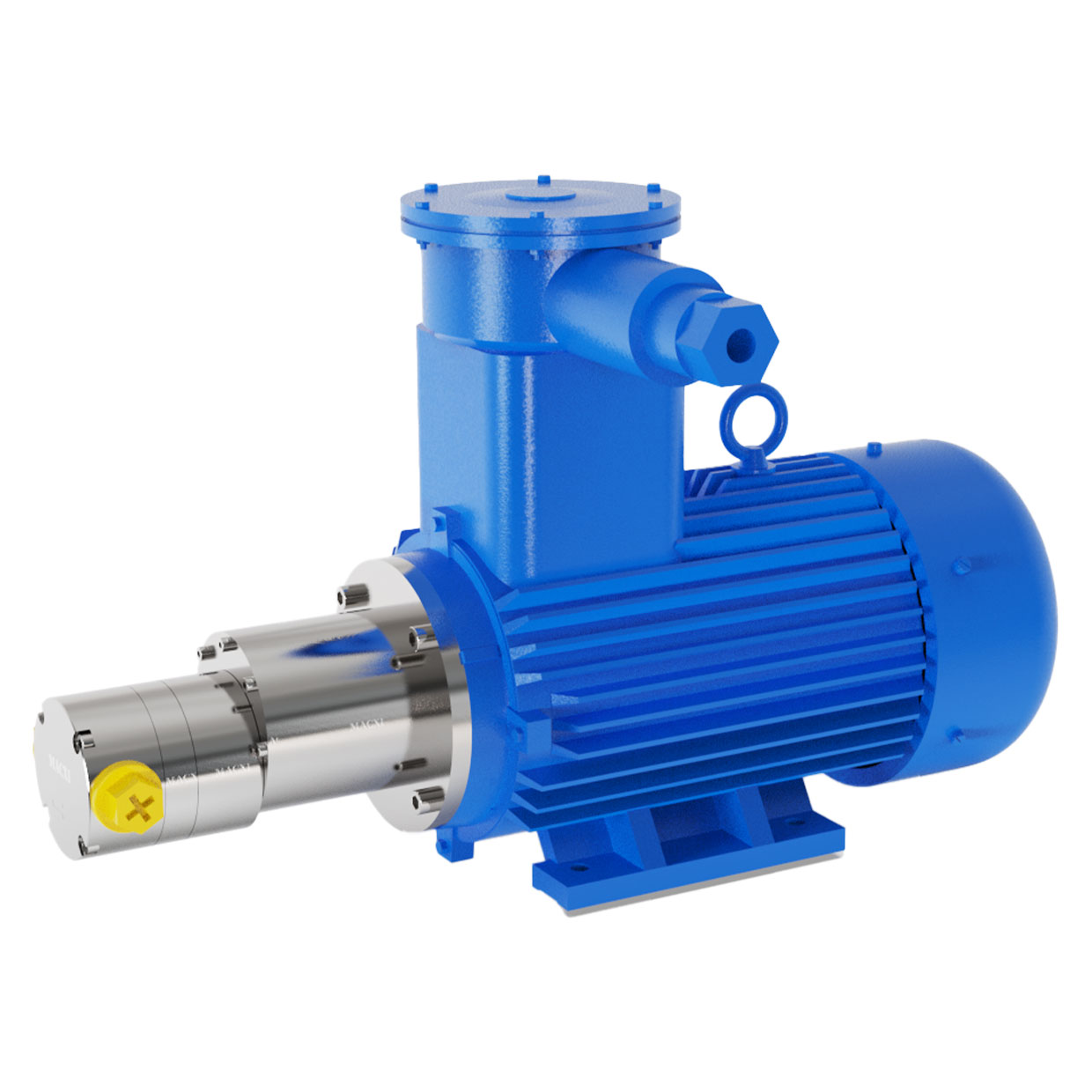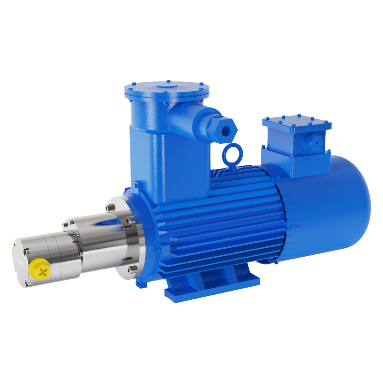
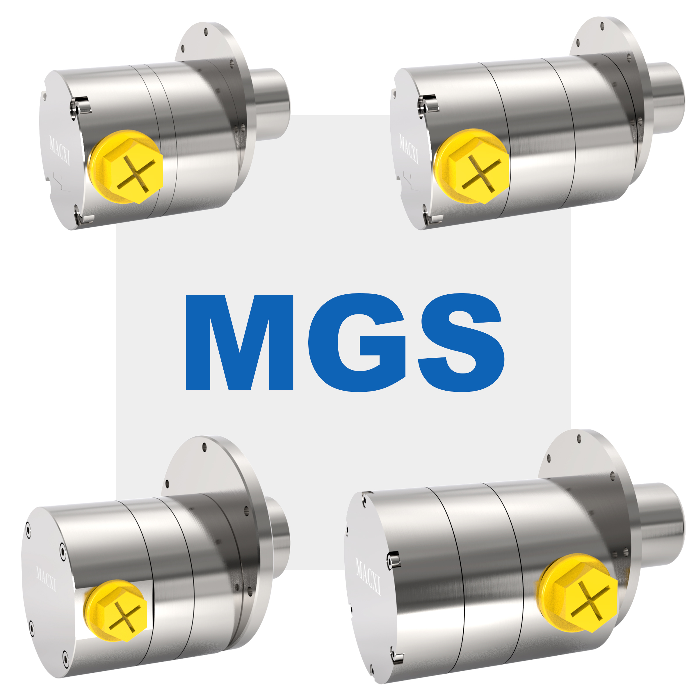
Belonging category:MGS high-pressure magnetic gear pump
Model:MGS
Flow range:0.32-140L/min
Voltage resistance:3Mpa
The pump body is made of food grade 316L, and the gear and shaft sleeve are made of modified high-strength PEEK. The gear pump adopts an "O" ring seal as a whole, with an overall pressure resistance of over 3MPA. The internal and external magnets adopt a dual magnetic tile design, greatly increasing the magnetic torque of the magnetic coupling. Some products can have a pressure difference of over 4MPa (it is recommended to use below 2MPa, as working with a pressure difference of over 2MPa will reduce the service life of the pump). It is suitable for most solvents, acids and bases, organic halides, hydrocarbons, organic nitrides, inorganic reagents, etc.
No leakage; Low noise; Long service life; Corrosion resistance; Stable export pressure without pulsation; Simple structure and easy maintenance.
Micro cooling devices for aerospace vehicles, chemical and chemical industries (such as reagents, pharmaceuticals, film manufacturing, pharmaceutical equipment, etc.), various laser equipment and instruments, printing and coding machine manufacturing, high-performance color printing equipment, charging pile liquid cooling systems, molecular distillation equipment, methanol to hydrogen equipment, exhaust gas treatment systems, etc.
Asynchronous motors, servo motors, etc.
PUMP INSTALLATION
The installation position of the pump should be as close as possible to the medium source container. The diameter of the inlet and outlet pipelines should not be smaller than the size of the pump interface, and the length should be shortened as much as possible. If the inlet pipeline needs to be lengthened due to layout and installation site space limitations, the inlet diameter should be increased and the number of valves and bends at the pump inlet should be minimized as much as possible.
PIPELINE INSTALLATION
During pipeline installation: 1. Align with the inlet and outlet of the pump body as much as possible, and if possible, add pipeline support at appropriate positions; 2. Avoid the eccentric torque and weight of the pipeline directly acting on the pump, otherwise it may affect the sealing of the pump body, and long-term external forces can easily cause damage to the pump body and leakage.
Installation diagram

FILTER
The inlet of the pump should be equipped with a 25um or higher precision filter (preferably 400 mesh or higher precision). If the pump operates in a closed-loop system, the filter can also be installed at the outlet of the pump. It is recommended that the nominal flow rate of the filter be 1.5 times greater than the maximum flow rate of the pump to ensure the flow area of the medium and reduce the impact of the filter on the flow resistance of the pipeline.
USE PRESSURE
It is recommended to use within the pressure range that the pump can withstand. 1. Excessive system pressure can affect the sealing effect of the pump body; 2. Excessive pressure difference between imports and exports can cause magnetic slippage inside and outside the magnetic coupling. Excessive pressure fluctuations during use can also easily cause slippage in magnetic couplings.
SELF SUCTION
Gear pumps have strong self-priming function, but before starting, confirm that the gears have been wetted by the pumped medium.
DRY/REVERSE
Long term over speed drying can cause permanent damage to the pump. Please confirm that there is medium in the pump chamber or at least it has been wetted during operation. The pump should rotate clockwise. Short term reversal is acceptable, but prolonged continuous reversal will shorten the lifespan of the pump.